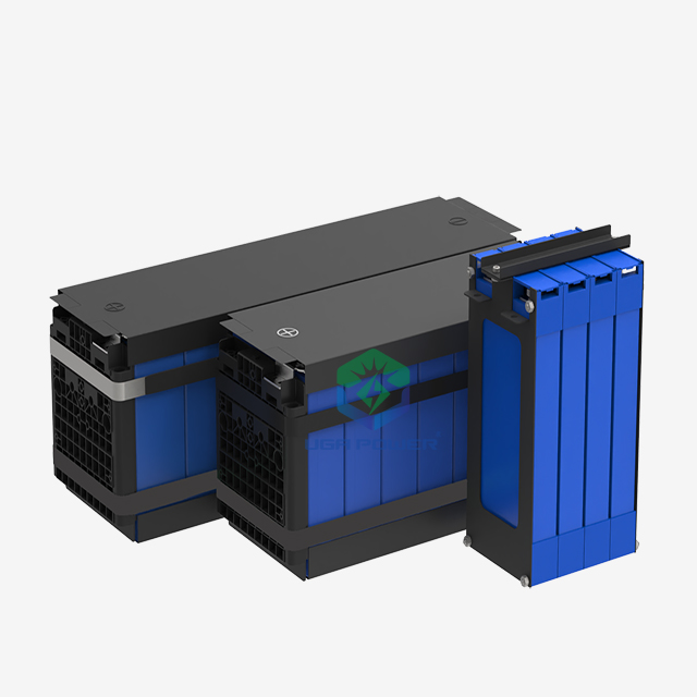
A Battery Management System is far more than a simple electronic component. It operates as the critical risk-mitigation engine for modern energy storage. Think of it as the ultimate safeguard for your commercial lithium-ion assets. Without an enterprise-grade controller, battery packs face catastrophic failure risks. Thermal runaway can destroy equipment and facilities in mere minutes. Furthermore, unprotected cells suffer from accelerated degradation and severe compliance liabilities.
You simply cannot afford to leave these dense energy reserves unmonitored. This guide moves beyond basic definitions. We provide a rigorous evaluation framework designed specifically for engineering and procurement teams. You will learn exactly how to select the right controller for your commercial or industrial deployments.
We cover hardware topologies, core algorithms, and real-world integration challenges. By the end of this article, you will possess the operational knowledge needed to protect your assets and guarantee continuous performance.
Key Takeaways
A BMS acts as the centralized "brain" of a battery pack, dictating safety, longevity, and performance through real-time monitoring and software algorithms.
Core functions include cell balancing, thermal management, and calculating critical metrics like State of Charge (SoC) and State of Health (SoH).
Selecting a BMS requires mapping hardware topologies (centralized vs. distributed) against application scale, wiring constraints, and cost.
Procurement evaluation must prioritize communication protocol compatibility (e.g., CAN bus), regulatory compliance (UL, ISO), and algorithm accuracy over time.
1. The Business Case: Why a BMS is Non-Negotiable
Catastrophic Risk Mitigation
Lithium-ion chemistries hold immense energy density. Uncontrolled release of this energy causes thermal runaway. Over-voltage conditions can rapidly ignite cells. Under-voltage situations dissolve internal copper components, permanently ruining the cell architecture. Industrial and EV applications rely heavily on safety mechanisms to prevent these scenarios. A specialized Battery Management System isolates the pack the millisecond it detects dangerous anomalies. Failing to implement these safeguards invites massive financial liabilities, equipment loss, and facility damage.
Asset Lifespan Optimization
Temperature and voltage limits define a cell's safe operating window. Staying within these strict boundaries extends cycle life significantly. It actively protects your initial capital investment. Pushing cells beyond their thermal limits degrades the internal chemistry prematurely. Advanced controllers constantly throttle charge and discharge rates based on real-time cell temperatures. You want your energy assets lasting a decade, rather than burning out in two years.
Operational Uptime & Telemetry
Predictive maintenance completely changes industrial operations. Modern controllers beam telemetry data directly to cloud dashboards. You can spot failing modules before they shut down a vehicle or a facility. This continuous data stream prevents unexpected system downtime. Engineering teams can schedule routine maintenance during off-hours, maximizing daily operational uptime. The controller turns a static energy box into a transparent, measurable asset.
2. Core Functions: What a Commercial-Grade BMS Actually Does
State Estimation Algorithms
Accurate fuel-gauging proves highly complex in industrial applications. Standard voltage readings fail because modern chemistries, like Lithium Iron Phosphate (LFP), feature extremely flat discharge curves. The State of Charge (SoC) requires advanced software models to track capacity accurately. Engineers utilize Coulomb counting combined with Kalman filtering to eliminate measurement errors.
State of Health (SoH) and State of Power (SoP) track degradation over time. They predict the end-of-life timeline and dictate safe power output limits. As internal resistance grows over years of usage, the algorithms adjust allowable discharge rates to prevent overheating.
Cell Balancing Mechanisms
Cells inside a pack never degrade perfectly evenly. Balancing ensures no single cell bottlenecks the entire pack's capacity.
Passive Balancing: This method bleeds excess energy as heat via resistors. It remains highly cost-effective and common across most commercial packs. However, generating excess heat requires robust thermal design. Active Balancing: This method shuttles energy directly between cells using capacitors or inductors. It offers higher efficiency and handles mismatched cells beautifully. Expect higher hardware complexity and steeper costs.
Balancing Method
Operational Mechanism
Energy Efficiency
Hardware Cost Profile
Passive Balancing
Bleeds high-cell energy as heat
Low
Highly cost-effective
Active Balancing
Shuttles energy to low-capacity cells
High
Premium pricing
Thermal Management
A localized hotspot can ruin a pack. The controller monitors cell temperature gradients meticulously. It interfaces directly with external cooling or heating systems. When a Battery Management System detects high thermal loads during rapid acceleration, it triggers liquid cooling pumps or fans. Conversely, it activates internal heating pads during freezing conditions to prevent lithium plating during charging.
3. Hardware Topologies: Structuring Your Architecture
Hardware layout dictates how your system scales. You must match the architecture to your physical constraints and voltage requirements.
Centralized BMS:
This layout places all control electronics on a single board. Sensor wires run from every single cell directly to this central brain. Pros: Highly cost-effective, extremely compact, and offers a single point of processing. Cons: Heavy wiring complexity creates a messy assembly process. It is poorly suited for large-scale or high-voltage packs where long wire runs cause measurement noise.
Modular / Master-Slave BMS:
This architecture splits duties. Slave boards monitor individual battery modules. A master board communicates with all the slaves and controls the main power contactors. Pros: Highly scalable and features simplified local wiring. You can easily replace a single faulty module without tearing down the entire system. Cons: Higher hardware costs. It absolutely requires robust, noise-immune inter-module communication protocols to function safely.
Distributed / Daisy-Chain BMS:
This structure mounts a tiny circuit board directly onto every single cell. The boards connect in a long daisy-chain back to a central controller. A large-scale Battery Management System often employs this for grid storage. Pros: Absolute minimum wiring complexity. It offers the highest scalability for massive installations requiring precise cell-level monitoring. Cons: Extremely complex troubleshooting. If the daisy-chain communication wire breaks somewhere in the middle, locating the exact fault becomes difficult. It also drives up the per-cell hardware cost.
4. Evaluation Framework: How to Select the Right Battery Management System
Voltage and Current Scalability
You must match the controller's ratings directly to your continuous and peak discharge requirements. Ensure the internal contactors or MOSFETs can handle the heat generated during maximum load. A common mistake involves sizing the hardware for continuous current while completely ignoring short-duration peak loads. Evaluate the pre-charge circuitry carefully. Improper pre-charge designs will weld your main contactors shut during startup.
Communication Interfaces
A controller cannot exist in a vacuum. It must ensure seamless integration with legacy inverters, proprietary external chargers, and centralized vehicle control units. Evaluate CAN bus compatibility for automotive or mobile applications. Look for Modbus or TCP/IP capabilities for stationary energy installations. Clear communication prevents overcharging and ensures smooth power delivery.
Software Flexibility & Tuning
Hardcoded algorithms create massive deployment headaches. Assess whether the vendor allows custom parameterization of the SoC and SoH algorithms. Different cell chemistries demand unique voltage curves and temperature limits. An algorithm tuned for NMC cells will completely misread an LFP cell's state of charge. Flexible software tools let your engineering team tweak variables as they gather real-world testing data.
Compliance & Safety Standards
Mandatory certifications dictate market entry. You cannot sell uncertified equipment in most commercial sectors. For automotive applications, prioritize ISO 26262 functional safety standards. For stationary energy storage and large industrial packs, look for UL 2580 or UL 1973 certifications. These labels prove the hardware survived rigorous physical and electrical abuse testing.
5. Implementation Realities and Integration Risks
Theory often clashes with reality during assembly. Expect severe friction when integrating electronic components from different vendors.
The "Soft-Hard" Integration Gap: Pairing third-party hardware with proprietary battery modules creates conflict. External chargers often struggle to interpret safety handshakes from unrecognized controllers. You will likely spend weeks rewriting communication headers to establish reliable data links.
Algorithm Drift: Poorly calibrated software models inevitably drift over time. If a pack undergoes months of partial cycling without reaching a full 100% charge, the SoC counter loses its baseline reference. This drift leads to false capacity readings. The dashboard might display 40% capacity, but the pack suddenly dies three minutes later.
Data Latency Limitations: Physics dictates how fast sensors can operate. CAN bus networks can experience severe congestion during rapid charge or discharge events. If the network drops packets, the main controller receives outdated voltage readings. High data latency delays safety shutdowns, potentially allowing a cell to exceed its maximum voltage threshold for a fraction of a second. Over time, these micro-exposures degrade the chemistry.
6. Next Steps: Shortlisting and Prototyping
Defining Success Criteria
Begin by mapping your strict technical requirements directly to your business constraints. Document the required continuous current, maximum peak current, and desired hardware topology. Contrast these technical needs against your budget limits and your required time-to-market. A custom-built controller offers perfect integration but delays your launch by a year. Off-the-shelf units deploy quickly but might require compromising on specific telemetry features.
Vendor Vetting
Do not simply look at the spec sheet. Ask potential suppliers hard questions regarding supply chain stability. Global chip shortages have ruined many production timelines recently. Inquire about their firmware update processes. Can they push over-the-air updates to fix bugs in the field? Finally, assess their post-sales integration support. A responsive engineering support team saves you months of troubleshooting frustration.
Pilot Testing
Never scale production before validating the hardware physically. Integrate your shortlisted controller with a small-scale prototype pack first. Run it through extreme temperature profiles in a thermal chamber. Deliberately trigger over-voltage scenarios to ensure the contactors open immediately. Validate the SoC algorithm against actual load bank data. Once the prototype passes these aggressive tests, you can safely proceed to full commercial rollout.
Conclusion
A commercial-grade controller serves as the defining factor between a safe, high-performing energy asset and a dangerous, degrading liability. It orchestrates the internal chemistry, optimizes daily performance, and acts as the ultimate safety firewall. Without precise algorithms and robust hardware, your investment remains vulnerable to premature failure.
Decision-makers must prioritize seamless system compatibility, proven algorithm accuracy, and rigorous safety compliance. Do not let raw hardware costs dictate your procurement strategy. Establish strict success criteria, vet your vendors thoroughly, and run aggressive pilot tests. By taking these methodical steps, you ensure your energy storage systems deliver reliable, long-term power.
FAQ
Q: Can I operate a lithium-ion battery without a BMS?
A: No. Operating a "dumb" lithium pack invites severe safety risks. Without continuous monitoring, individual cells will quickly drift out of balance. This inevitably leads to dangerous over-voltage charging or under-voltage discharging. In worst-case scenarios, lacking safety cut-offs directly causes thermal runaway, fires, and rapid chemical degradation.
Q: What is the difference between active and passive cell balancing?
A: Passive balancing simply bleeds excess energy from high-voltage cells as heat using internal resistors. It is highly cost-effective but wastes energy. Active balancing uses specialized circuitry to shuffle energy from higher-charged cells directly into lower-charged cells, maximizing efficiency but increasing hardware costs.
Q: How does a BMS calculate State of Charge (SoC)?
A: It relies on a combination of techniques. Basic models use simple coulomb counting to measure energy entering and leaving the pack. Advanced algorithms combine this counting with voltage lookup tables and Kalman filtering. These complex math models correct measurement drift and account for temperature variations in real-time.
Q: Why do Battery Management Systems fail?
A: Failure typically stems from extreme electrical or physical abuse. Common points of failure include blown MOSFETs from unanticipated current spikes, degraded sensor wires due to heavy industrial vibration, and software bugs that cause contactors to lock up. Moisture ingress can also short out the main logic board.